Troubleshooting Frame Relay Networks

Once a frame relay line has been properly provisioned by the
provider, the installation of a frame relay network using Cisco
routers is usually a trouble-free task involving minimal
configuration. However, if problems arise in the frame relay
network, proven techniques can be applied to isolate and solve
them. Troubleshooting a frame relay network problem can be broken
down into four easy steps.
- Verify the physical connection
between the DSU/CSU and the router
- Verify that the router and
frame relay provider are properly exchanging LMI
- Verify that the PVC status is
active
- Verify that the frame-relay
encapsulation matches on both routers
Cisco routers offer extensive diagnostic tools to assist in
the above tasks. However, most frame relay problems can be
diagnosed by using the following simple commands:
Step 1: Verify the physical connection between the
DSU/CSU and the router
Above all else, a good physical connection must exist between
the router and the local DSU/CSU. The show interface command can
be used to determine the status of the physical connection.
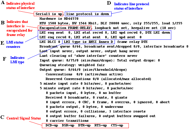
Figure 1 is a sample output of a "show interface
serial1" command.
Figure 1 -
"show interface serial1" Output

Referring to the figure above, the field marked with an
"A" indicates the physical status of the interface. An
interface can be in one of three possible states - up, down, or
administratively down. The table below outlines the possible
states and offers some suggested actions to correct physical
connection problems.
| Interface State |
Problem Description And Suggested Actions |
| Serial x is up |
This indicates that the interface has a good
connection to the DSU/CSU. Proceed to step
2. |
| Serial x is administratively down |
This indicates that the interface is in shutdown
mode. The following commands are used to take an
interface out of shutdown:
- Router# config term
- Router(config)# interface serial x
- Router(config-if)# no shutdown
- Router(config-if)# exit
|
| Serial x is down |
This indicates a poor physical connection to the
DSU/CSU because the router is not receiving all of the
control signals from the DSU/CSU. The show interface
command will display which control signals are missing
(see field "C" in figure 1). A missing signal
will be indicated with a "down" state (e.g.
DCD=down). Suggested Actions:
- Verify that the cable is securely
inserted into the serial interface on the router.
- Verify that the cable is securely
inserted into the DSU/CSU DTE port.
- The DSU/CSU may need to be configured to
properly assert the control signals (DSR, RTS,
DCD).
With some DSU/CSUs, DSR needs to
be set to properly reflect DCD. This will vary
depending on DSU/CSU manufacturers. Check the
DSU/CSU documentation.
- The cable, router's serial port, or
DSU/CSU's serial port may not be functional.
If
possible, first try moving the cable and
configuration to an unused serial port on the
router. This will isolate the problem to or away
from a faulty router port. Next, try swapping the
serial cable. This will isolate the problem to or
away from a cable issue. Finally, try swapping
out the DSU/CSU.
|
Step
2:
Verify that the router and frame relay provider are properly
exchanging LMI
Once a good physical connection
has been established between the router and the local DSU/CSU,
the next goal is to verify that the line protocol is up between
the router and the frame relay provider. For a frame relay
network, the line protocol is the periodic exchange of local
management interface (LMI) packets between the router and the
frame relay provider. The first line of the show interface
command will indicate if line protocol is up or down (see field
"D" in figure 1) indicating if LMI is properly
exchanging or not. The table below outlines the possible
line protocol states and offers some suggested actions to correct
line protocol problems.
| Line Protocol State |
Problem Description And Suggested Actions |
| line protocol is up |
Frame relay LMI is properly exchanging between the
router and the frame relay provider. Proceed to step 3. |
| line protocol is down |
LMI is not properly exchanging between the router and
the frame relay provider. Suggested Actions:
- Verify that the router's LMI type matches
the LMI type used by the frame relay provider.
The
only parameter that can be configured on the
router that relates to the line protocol is the
LMI type. Once the router is configured with the
proper LMI type, all other line protocol problems
depend on the DSU/CSU settings or carrier
provisioning. The router's LMI type can be
verified with either the show interface command
(see the field marked "F" in figure 1)
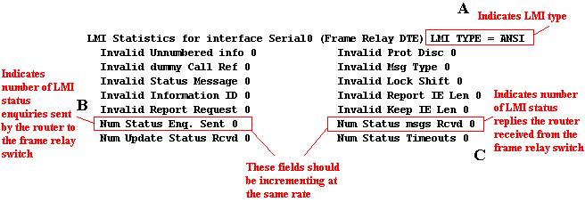
or the show frame-relay lmi command (see the
field marked "A" in figure 2).
Note: If the frame relay provider is using
"ANSI Annex-D" LMI, configure the
router to use "frame-relay lmi-type
ansi". Also, be aware that frame relay
providers often generically refer to
"lmi-type cisco" as simply
"LMI". If the frame provider states
that they are using LMI type "LMI",
make sure the router is configured to use
"frame-relay lmi-type cisco".
- Verify that the router is sending LMI
packets to the frame relay provider
This
is a sanity check to make sure the router is
doing its half of the LMI exchange. Use either
the "show interface" command (see field
"E" in figure 1) or the "show
frame-relay lmi" (see fields "B"
and "C" in figure 2) repetitively to
determine if the router is sending LMI packets to
the frame relay switch. The "Num Status Enq.
sent" counter will increment every ten
seconds if the router is attempting to send LMI
packets. If this counter is not incrementing,
reverify physical connections and make sure the
interface is not in shutdown. Alternatively, the
"debug frame-relay lmi" command can be
used to actively monitor the exchange of LMI
packets.
Note: The "Num Status Enq. sent"
counter will increment at the same rate as the
"Num Status msgs. Rcvd" counter if the
router is successfully exchanging LMI with the
frame relay switch.
- Verify that DSU/CSU parameters are
properly configured.
The successful
exchange of LMI packets between the frame relay
switch and the router relies upon the successful
delivery of frames by the DSU/CSU. The router
might be sending LMI packets (see actions 1 and 2
above), but this is meaningless if the DSU/CSU is
not forwarding these frames onto the frame relay
switch correctly. There are three main parameters
that MUST be correctly configured on the DSU/CSU
- clocking, framing, and line encoding. The frame
relay provider supplies this information.
Clocking: The clock source
can either be internally generated by the DSU/CSU
or supplied by the frame relay provider. For
frame relay networks, the DSU/CSU normally gets
its clocking from the network (i.e. frame
provider). Check with the frame relay provider
about the clock source and configure the DSU/CSU
accordingly.
Framing: A DSU/CSU can be
configured to frame data either in extended super
frame (ESF) format or super frame (D4 framing)
format. Ask the frame relay provider which data
framing they are using and configure the DSU/CSU
accordingly.
Line Encoding: A DSU/CSU can
be configured to use either alternate mark
inversion (AMI) encoding or binary eight zero
substitution (B8ZS) encoding. Usually, AMI is
associated with D4 framing and B8ZS is associated
with ESF framing. Check which type of line
encoding the frame relay provider is using and
configure the DSU/CSU accordingly.
- Verify that the frame relay provider has
turned the circuit on.
If none of the
above seem to work, it could be that the telco
has yet to turn on the frame relay circuit. Use
the "debug frame-relay lmi" command to
display whether the router is receiving LMI
responses from the frame relay switch or not.
Double check with the frame relay provider that
the circuit has been activated.
|
Figure
2
- "show frame-relay lmi" Output

Step
3:
Verify that the PVC status is active
Once the interface is up and
the line protocol is up, the next step is to verify that the PVC
status is active. To view the status of PVCs on the router, use
the show frame-relay pvc command. Figure 3 displays a sample
output of the show frame-relay pvc command.
Figure
3
- "show frame-relay pvc" Output

The show
frame-relay pvc command will indicate that the PVC is in one of
three different states (see field "B" in figure 3). The
table below outlines the possible PVC states and offers some
suggested actions to correct PVC problems.
| PVC Status |
Problem Description / Suggested Actions |
| Active |
A permanent virtual circuit (PVC) has been created.
The frame relay link between the two sites is up. Proceed
to step 4. |
| Inactive |
This status indicates that the PVC associated with
the corresponding DLCI number (see field "A" in
figure 3) is being offered by the frame relay provider,
but not being used by the router. Suggested
Actions:
- Verify DLCI numbering.
Double
check the DLCI numbering with the frame relay
provider and make certain that the router is
configured with the DLCI numbering that the frame
relay provider has supplied. The DLCI numbers are
configured with either the "frame-relay
map" command for multipoint interfaces or
the "frame-relay interface-dlci"
command for point-to-point subinterfaces. A
common mistake is the accidental reversal of DLCI
numbering between sites. For instance, if the
DLCI number that is supposedly assigned to the
remote site shows up as "inactive" at
the local site, there is a good chance that the
DLCI numbers are reversed.
|
| Deleted |
This status indicates that the router has been
configured with a DLCI number that is not offered by the
frame relay provider. As a result, the PVC cannot be
created and therefore is "deleted". Suggested
Actions:
- Verify DLCI numbering
Double
check the DLCI numbering with the frame relay
provider and make certain that the router is
configured with the DLCI numbering that the frame
relay provider has supplied. The DLCI numbers are
configured with either the "frame-relay
map" command for multipoint interfaces or
the "frame-relay interface-dlci"
command for point-to-point subinterfaces. A
common mistake is the accidental reversal of DLCI
numbering between sites. Check to see if there
are any other DLCI numbers showing up as
inactive. If there are inactive entries, there is
a good chance that the correct DLCI number should
be the DLCI number that is showing up as
inactive. Check with the frame relay provider to
be certain!
- Verify that the frame relay provider has
activated the PVC
There is a
possibility that the frame relay provider has not
yet activated the PVC. Check with the frame relay
provider to verify that the PVC has been
activated.
|
Step
4:
Verify that the frame relay encapsulation matches on both routers
Finally, if all of the above
steps have not solved the frame relay problem, the problem may be
related to frame relay encapsulation. Cisco routers default to
"cisco" frame relay encapsulation. "Cisco"
frame relay encapsulation is only valid between other Cisco
routers that are using "cisco" frame relay
encapsulation. If connecting to a third party router, the frame
relay encapsulation must be changed from "cisco" to
"IETF". To configure IETF frame relay encapsulation,
replace the "encapsulation frame-relay" command with
"encapsulation frame-relay IETF".
Most frame relay problems can be solved by following the steps
outlined in this document. If problems still persist after
following the above steps, the problem might not be related to
frame relay but rather related to the specific routed protocol.
All contents copyright © Cisco Systems, Inc. Important
notices.
![]()


