Media History and Overview
Ethernet originated in the 70's from efforts at Xerox's
PARC to create a new method for connecting computers together
for sharing programs, data and information
The first version of Ethernet was soon replaced by
Version II that was developed by a joint effort between Digital
Equipment Corp, Intel Corp and Xerox Corp. This is also know as
the DIX Ethernet standard
- Ethernet Version II has the following properties
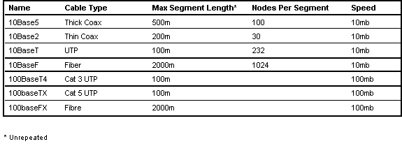
- uses thick coaxial cable
- operates at 10mb
- allows unrepeated cable runs up to 500m
- allows 100 devices per cable segment
- uses CSMA/CD for controlling access to the shared
media
- has a two byte protocol type field following
the mac source address
- minimum data length of 64 bytes and a maximum
length of 1500 bytes
- systems running Ethernet VII cannot talk to 802.3
systems unless they support both frame types concurrently

- CSMA/CD 802.3
- The IEEE eventually ratified a slightly different
version of Ethernet under the 802.3 standards track.
- The original 802.3 standard has the following
properties
- uses thick coaxial cable
- operates at 10mb
- allows unrepeated cable runs up to 500m
- allows 100 devices per cable segment 2.5 meters
apart
- uses CSMA/CD for controlling access to the shared
media
- is also known as (aka) 10Base5
- has a two byte length field following the mac
source address
- uses the 802.2 SAP fields to denote the protocol
in the frame
- minimum data length of 61 bytes and a maximum
length of 1496 bytes when using 802.2 LLC2 ABME
- systems running 802.3 cannot talk to Ethernet
VII systems unless they support both frame types concurrently

- CSMA/CD 802.3 additional media types
- 802.3 has been revised many times to add new
physical layer media
- 10Base2 has the following properties
- standard for thinner coax cable
- allows cable runs up to 185m
- cabling runs from station to station in a chain,
no concentrators
- aka cheapernet
- 10baseF (aka foirl) has the following properties
- standard for optical fiber
- allows significantly longer cable runs
- cabling is usually connected to a hub in a star
configuration
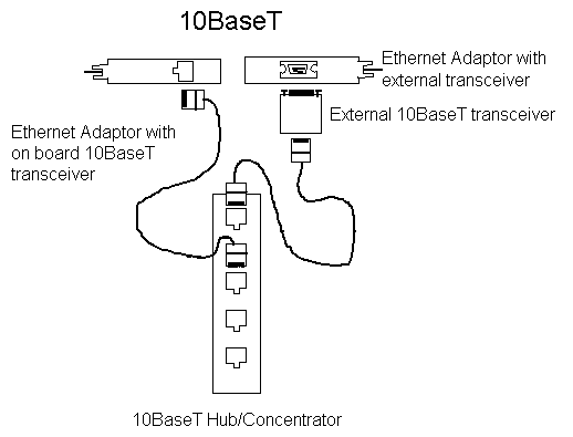
- 10baseT has the following properties
- standard for utp
- allows cable runs up to 100m
- cabling is usually connected to a hub in a star
configuration
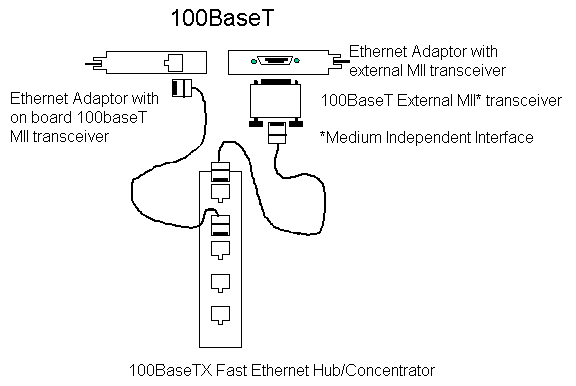
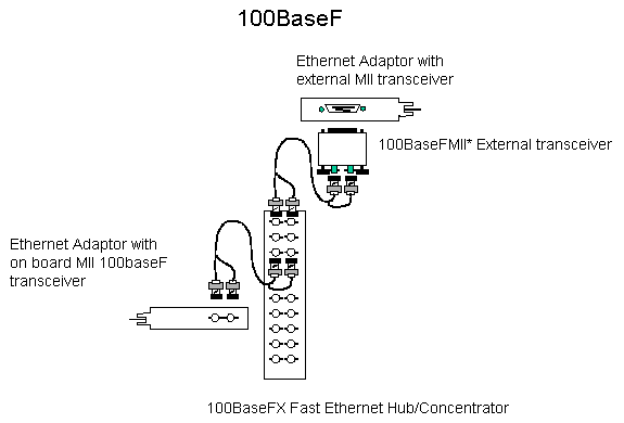
- 100baseF/T has the following properties
- operates at 100mb
- allows 100m cable runs on UTP (100baseT)
- allows significantly longer cable runs on fiber
(100baseF)
- cabling is usually connected to a hub in a star
configuration
- The IEEE is currently working on a new version
of 802.3 that will operate at 1 gigabit
- Cisco recently purchased Granite Systems to obtain
their gigabit ethernet technology
- CSMA/CD physical connectivity options
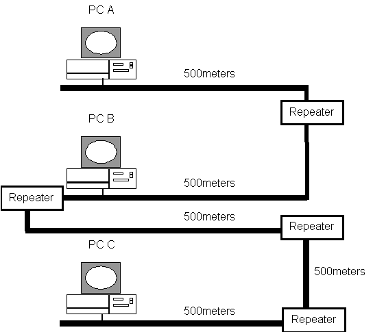
- As a rule it is possible to connect 5 10Base5
500 meter cable segments together. However stations can only attach
to three of the segments. It is fairly unusual to see end stations
directly attached to 10Base5 segments in this day and age. However
inter-connectivity devices such as routers and bridges are still
occasionally connected to a 10Base5 backbone.
- CSMA/CD simple view of how it works
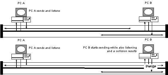
- PC A listens to see if any other station is already
transmitting prior to sending a frame. In the example above the
network was available so PC A transmitted its frame. PC B is also
listening. PC B sees the frame that PC A transmitted and checks
the destination MAC address to ss if the frame is addressed to
itself. Note that the transmission flows in both directions simultaneously.
The cable terminators at the end of the cable absorb the signal
and prevent it from echoing back down the cable. The arrow from
the cable back to the PCs is intended to indicate that the PCs
are listening even when they are transmitting to detect collisions.
- CSMA/CD a collision in action
In this example both PC A & PC B believed that
the network was available and started to transmit nearly simultaneously.
Neither PC heard the others transmissions right away due to the
propagation delay of the bits traveling on the cable. This causes
a collision. In this case PC B will detect the collision. PC
B stops transmitting and sends a JAM signal telling all devices
on the cable to back off and try again. PC A hears the JAM signal
and stops transmitting. Each device waits a period of time based
on the standardized back off algorithm and tries again.
The minimum packet length on an ethernet network
is 512 bits (64 bytes). This minimum length ensures that a stations
is still transmitting a frame when all other stations on the ring
have had an opportunity to see the frame and raise a collision
alert if necessary. Collisions raised by other stations tell a
transmitting station that its frame was not delivered and it will
have to try again.
- CSMA/CD a JAM signal in action
- Eventually both stations detect the collision
and send a JAM signal to
- indicate that a collision has occurred. Both
stations wait a random amount
- of time as calculated by the backoff algorithm
and try again.
- CSMA/CD out of spec cable causes problems
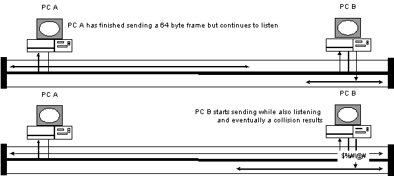
In this example PC A has just finished transmitting
a 64 byte frame onto the cable. PC B did not detect PC A's frame
even though it met the minimum size requirement. This can be caused
by an out of spec cable plant. Normally a 60 byte frame would
have filled up the entire cable and PC A would have still been
transmitting when PC B attempted to transmit. A collision would
have occurred and PC A would have known that it would have to
retransmit its frame.
In this case PC A has finished transmitting the frame
and removed it from its hardware buffers before PC B started transmitting
its own frame. Eventually PC B will detect PC A's frame and a
collision will result. PC A will detect the collision signal but
will not know that it was referring to the frame it just sent.
PC A will assume another station was the cause of the collision.
As far as PC B is concerned the frame it detects is just another
normal collision. PC B has no knowledge that this was in fact
a frame that PC A thought it had transmitted successfully.
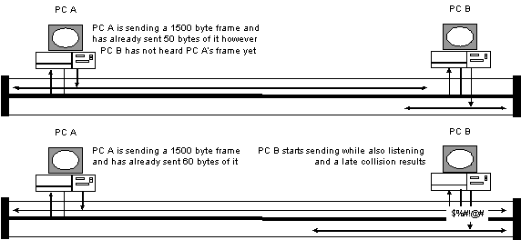
In this example both PC A has transmitted the first
60 bytes of its frame on the cable. As PC A has not heard a collision
for this frame yet it will continue sending the balance of the
frame. However PC B has not yet heard this frame. Possibly due
to an out-of -spec cabling system. PC B begins transmitting its
own frame. PC B will soon discover its mistake when it hears the
frame from PC A on the cable. PC B immediately issues a JAM signal.
PC A will hear the JAM and stop transmitting. PC A will log a
Late Collision because it should not have been able to get 60
bytes of a frame onto the cable before hearing a collision.
- CSMA/CD minimum frame size and cable length
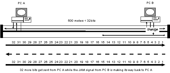
In fact the time it takes to transmit a 64 byte frame
onto a cable has to be greater than propagation delay of sending
a bit from from one end of the cable plant to the other and back.
This is because a station at one end may start sending a frame
while a station at the other end may also start sending a frame
at the same time. Each station must detect the other stations'
frame and send a JAM signal that must reach the originating station
while it is still transmitting its frame.
In other words a cable plant can only be <32bits
long in order to work successfully.
- 802.5 Token Ring
- IEEE 802.5 and Token Ring as described by the
IBM Token Ring Architecture Reference are very similar and essentially
compatible
- For this presentation Token Ring will be used
to mean either standard
- 802.5 does not specify a physical layer technology
like 802.3 does
- The original IBM specification called for Shielded
Twisted Pair (STP) wiring however IBM has now issued guidelines
for UTP and Fiber
- It is possible to connect Token Ring networks
with the following cable types
- STP
- CAT 3/4/5 UTP
- SM or MM Fiber
- Token Ring operates at either 4mb or 16mb regardless
of media type in use
- Not all vendors' CAT 3/4 UTP equipment supports
16mb properly
- Full Duplex 32mb (16mb each way, concurrently)
Token Ring is now a standard IEEE ?????
- Token Ring physical connectivity options
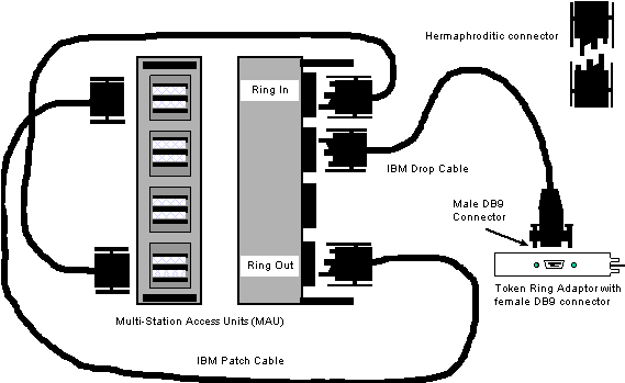
- IBM Originally used what is referred to as a
"hermaphroditic" connector.
- This connector could connect to other connectors
simple by flipping one
- of the two connectors over and clicking them
together. No gender
- benders were necessary. This made it easy to
make a STP patch cable longer. This diagram shows a classic IBM
Token Ring network. The Ring In of one MAU is connected to the
Ring Out of the other MAU and vice versa thus creating a physical
ring.
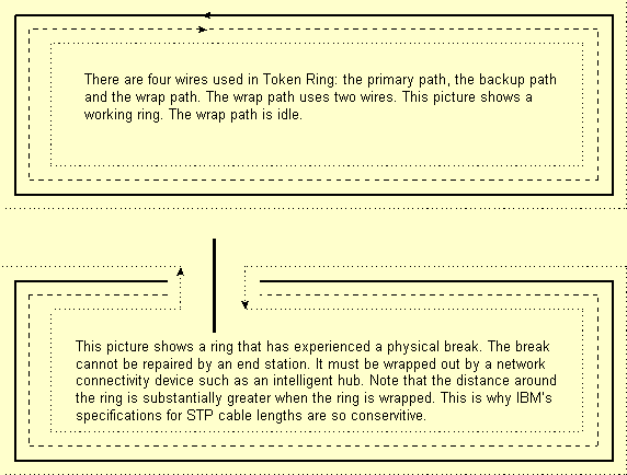
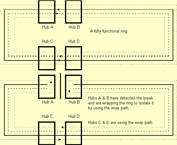
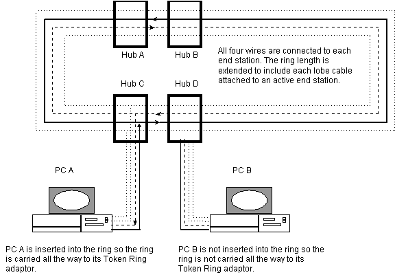
- Token Ring has a concept of ring repair similar
to FDDI although not as sophisticated. In Token Ring the end station
cannot wrap a ring link and FDDI station can. A broken Token Ring
must be wrapped by a device like an intelligent hub. The next
diagram shows how an intelligent hub wraps a ring.
- Token Ring physical layer issues
- Although the ring length is in fact extended
to the end stations the four wires are not labeled the same as
they are when interconnecting hubs. In the case of end systems
the wires are primary transmit and receive and backup transmit
and receive.
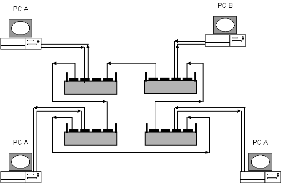
- Although Token Ring is in fact a "ring"
it is wired in a star configuration as depicted here. Remember
from the previous diagram that the "ring" extends out
to each active end station.
- The five phase insertion process for connecting
to an active token ring
The station sends frames to itself without inserting
itself into the ring. The frames are looped at the MAU. If the
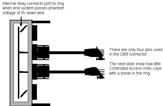
test passes the station sends a 5 volt signal down the lobe cable.
This opens the relay and inserts the station onto the ring.
If no active monitor is present this station will
become the active monitor.
Duplicate MAC addresses are not allowed on the same
ring. If the station detects another station with the same address
already on the ring it will not insert itself into the ring.
This is the process where each station on the ring
discovers its upstream and downstream neighbors. This information
is used for isolating fault domains.
- Request Initialization from RPS if present
- If there is an RPS on the ring it will provide
information about the ring to a station in the RPS response. The
RS can also prevent stations from inserting by implementing security
restrictions configured by an administrator.
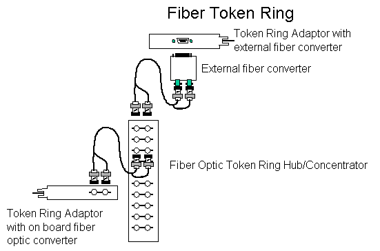
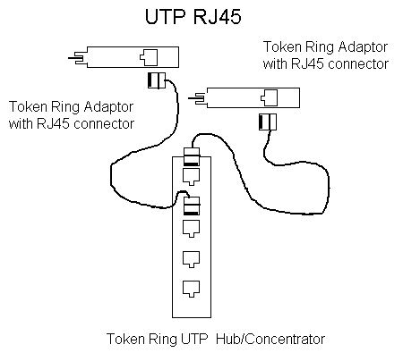
- Other Token Ring physical connectivity options
Copyright 1992-1999 © Cisco Systems Inc.


